The structure of TFT LCD display
Liquid Crystal Panel (Panel): This is the main part of the display, responsible for presenting the image. The liquid crystal panel is formed by two glass plates with a layer of liquid crystal sandwiched between them, known as the liquid crystal cell.
Polarizing filters: These components are located on both sides of the liquid crystal cell and are tasked with processing the light that passes through the cell.
Color Filter: Usually fabricated on one of the glass plates of the sealed liquid crystal cell, this is used for color display.
Thin Film Transistor Array (TFT Array): Positioned on the other glass plate of the sealed liquid crystal cell, it plays an active role in driving the display.
Backlight: The light source located behind the TFT-LCD display module provides the light necessary for the visible image to be produced through the liquid crystal cell.
External Drive Circuitry: These circuits are in charge of managing the input image signals to appropriately drive the TFT array and backlight.

The manufacturing process of TFT LCD displays
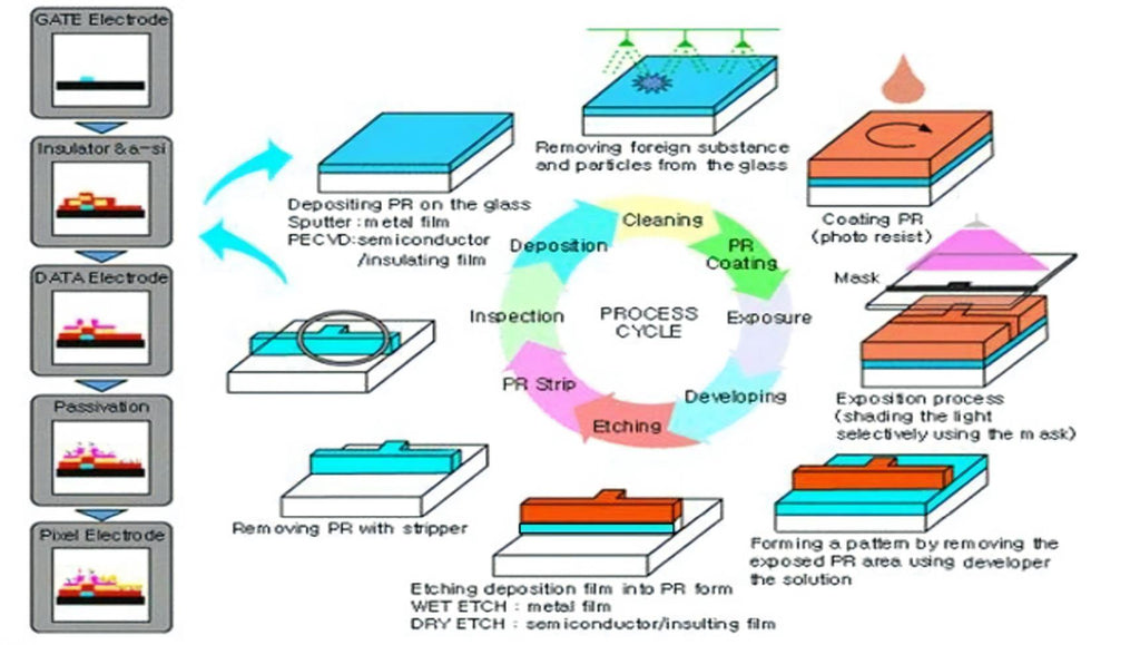
Film Formation: Techniques like Sputtering (SPT) and Chemical Vapor Deposition (CVD) deposit multiple layers on the substrate.
Photolithography: Applying, exposing, and developing photoresist to form microstructures.
Etching: Wet and dry etching methods sculpt the substrate by removing specific areas.
Stripping: Post-patterning, excess materials are removed to clean the substrate.
Auxiliary process steps:
Cleaning: Ensures the substrate is free from contamination.
Marking and Exposure: Identifies and prepares the substrate edges.
Automated Optical Inspection (AOI): Used for defect inspection.
Microscopic Inspection and Macroscopic Inspection (Mic/Mac): Detail checking.
Film Performance Testing: Uses tools like sheet resistance meters, profilometers, reflectometers/ellipsometry, Fourier-transform infrared spectroscopy.
Open/Short (O/S) Electrical Testing: Checks for circuit continuity and shorts.Test Element Group (TEG) Electrical Testing: Tests the electrical performance of elements.
Array Electrical Testing: Ensures the array’s electrical functionality.
Laser Repair: Corrects any defects according to inspection results.
Photoresist Rework (PR Rework): Adjusts or repeats the photolithography steps if necessary.
Film Rework: Changes or perfects the film formation process if necessary.

OC Layer protects and prepares the color filter patterns.
RGB Layer formation via coating, exposure, and development sequences.
BM (Black Matrix) Layer enhances contrast and limits light leakage.
PS (Photo Spacer) Layer maintains precise gap between substrates, crucial for image quality.
ITO Layer adds a transparent conductive film for electrical conduction and touch functionality.

Polyimide (PI) Alignment & Orientation: Applying and orienting the PI layer for liquid crystal alignment.
ODF (Optical Display Film) improves visual effects.
Cleaning and Frame Sealant Application: Preparing for liquid crystal droplet insertion.
Liquid Crystal Injection: Precisely dispensing the liquid crystal on the display.
TFT & CF Lamination: Bonding the TFT and CF components together.
UV Curing & Thermal Processing: Solidifying and evenly distributing the liquid crystal with ultraviolet light and heat treatment.
Cutting, Electrical Testing, & Edge Smoothing: Shaping the substrate, performing electrical checks, and smoothing edges.
Polarizer Attachment & Debubbling: Applying polarizing films and eliminating air bubbles, with rework allowed if necessary.

Laser Cutting & Electrical Testing: Ensuring precise shape and electrical integrity.
COG (Chip On Glass) Bonding, FPC (Flexible Printed Circuit) Bonding & Testing: Installing and testing the driving circuitry.
Assembly & Electrical Testing: Combining all display module parts and performing final electrical tests.
Aging: Long-term power supply to ensure product reliability.
Packaging & Shipping: Preparing the finished product for delivery.

Array segment flow
G: The gate insulator, made of SiNx (Silicon Nitride), provides necessary insulation between the gate and other layers.
I: The channel layer, a-Si (amorphous Silicon), where the electronic switching takes place.
N: The n+ a-Si layer is doped with a high concentration of Phosphine (PH3). This doping reduces the potential barrier at the interface, ensuring an Ohmic contact which is crucial for reliable device operation.

Gate Metal (AlNd/MoN)
 1. Initial Material Inspection (IQC): This step sees a preliminary inspection performed on incoming materials and components, ensuring they meet quality standards.
G I N (SiNx / a-Si / n+ a-Si)
 1. Island Chemical Vapor Deposition (ISCVD) - Non-metallic materials are deposited on designated areas of the substrate through the chemical vapor deposition method to form semiconductor islands.
S/D Metal (Mo \Al\Mo)
The formation of the source and drain electrodes (S/D), data electrode, and channel includes specific procedures such as layering with Molybdenum Nitride (MoN) and pure Aluminium (for source and drain), sputtering of the S/D metal layer, S/D photolithography, S/D wet etching, and channel dry etching. Through these processes, the source and drain electrodes, channel, and data lines of the TFT form on the glass substrate. At this stage, the construction of the TFT is concluded. The resulting design and process are as follows:

S/D Sputtering: This is a crucial step to form source/drain electrodes. During this process, a dense layer of metal electrodes is formed by sputtering heavy metal ions onto the substrate.
Cleaning before PR Coating: Before applying photoresist, the substrate must be cleaned to remove dust and residues, ensuring good coating results.
DHP (Hot Plate): To better attach the photoresist to the substrate, the substrate is pre-heated on a hot plate before the coating process.
Resist Coating: Apply a layer of photoresist to the pre-heated substrate, which is used for subsequent patterning.
Pre-curing (SHP): The photoresist coated substrate is pre-cured to make the photoresist more uniform and stronger.
Stepper Exposure: In this step, the amount of light exposure is controlled to harden certain areas of the photoresist and create the desired pattern.
Developing: The exposed photoresist is processed to reveal the pattern.
Photoresist Post Baking (HHP): The photoresist pattern is further hardened and made more prominent through another heating process. This can also improve its ability to resist chemical corrosion and wear.
Developing Inspection: After developing, a detailed inspection is needed to ensure the accuracy of the pattern and promptly detect and address any issues.
Wet Etching: This is a chemical reaction process where a corrosive liquid is used to etch the material in the non-protected areas to form the circuit pattern.
Channel Dry Etching: A channel is formed between the source and drain. In this process, the silicon in the channel region is etched into the required shape using a dry etching technique.
Resist Strip: Finally, to clean the substrate surface, the photoresist on the substrate is stripped off.
After the above steps, the source/drain electrodes, data electrodes, and channel of TFT are finally formed on the glass substrate.

Passivation (SiNx)
The formation of the passivation layer (SiNx), often known as the protective insulation layer, along with the vias, includes specific operations such as PECVD film formation, photolithography, and dry etching for via creation. After going through these procedures, the protective insulation layer for the TFT channel and the conductive vias are finally formed on the glass substrate. The images and the process obtained after the completion of these steps are as follows:

2. Pre-Coating Cleaning - This is where the substrate is cleaned prior to photoresist application.
3. Hotplate Prebake (DHP) - This involves using a hotplate to preheat the substrate to prepare for the coating step.
4. Photoresist Coating - A layer of photoresist gets applied over the substrate during this stage.
5. Soft Bake (SHP) - The substrate, coated with photoresist, undergoes a pre-cure process to solidify the layer.
6. Stepper Exposure - Here, stepper lithography technology is used to expose the photoresist and form patterns.
7. Developing - The exposed photoresist is processed to reveal the pattern.
8. Hard Bake (HHP) - The photoresist pattern is hardened through a post-bake treatment.
9. Post-Develop Inspection - This stage involves inspecting the developed substrate to confirm the accuracy of the patterns.
10. Wet Etching - Unwanted thin film materials are removed via a wet chemical etching process to create circuit patterns.
11. Photoresist Stripping - The photoresist is removed and the substrate’s surface is cleaned.
12. Contact Hole Etching (CH Etching) - The required vias are formed through a dry etching process.
These are the detailed steps involved in preparing the substrate for TFT applications, leading to the protection of the active TFT channel and the formation of conductive vias.
Formation of transparent pixel electrode ITO(Indium-Tin-Oxide)
The creation of transparent pixel electrodes in TFT displays is a sophisticated process, beginning with the deposition of Indium-Tin-Oxide (ITO). The stages involved are precision-engineered and include sputtering the ITO layer to achieve transparency, followed by photolithography for intricate patterning, and concluded with wet etching to finalize the pixel structure. This meticulous sequence concludes with the formation of the pixel electrodes, flawlessly integrated onto the glass substrate, marking the pivotal completion of the array process. The following workflow details the refinement and sequence of operations post-process completion.

Pixel Layer Deposition (ITO Sputtering) – Establishes a transparent conductive film of ITO (Indium Tin Oxide) for subsequent pixel patterning.
Substrate Cleaning (Pre-Resist Coating Clean) – Ensures substrate purity prior to applying the photoresist material.
Substrate Preheating (Dehydration Hot Plate, DHP) – Prepares the substrate with a pre-bake step for optimal photoresist adhesion.
Resist Application (Coating) – Applies a uniform photoresist layer on the substrate.
Soft Bake (Pre-curing SHP) – Conducts pre-curing to solidify the photoresist before patterning.
Precision Exposure (Stepper Exposure) – Utilizes stepper photolithography to expose the photoresist, creating the desired pattern.
Pattern Development (Developing) – Develops the exposed photoresist to reveal the intricate pixel pattern.
Resist Harden (Post-exposure Bake, Hard Bake HHP) – Hardens the patterned photoresist to improve etch resistance.
Pattern Inspection (Post-develop Inspection) – Inspects the developed patterns for accuracy and integrity.
Pattern Transfer (ITO Etching) – Transfers the pattern through etching the ITO layer to form pixel electrodes.
Resist Removal (Strip) – Strips away the photoresist, leaving a clean substrate surface.
Performance Enhancement (Annealing) – Anneals the components to enhance the electrical properties of the thin-film transistors.
Quality Control (TEG Test) – Performs electrical tests on test elements to monitor quality during production.
This streamlined sequence lays the groundwork for high-quality TFT displays with optimal electrical performance.

Color Filter (CF) process
Glass Substrate: The foundational base layer that renders mechanical support.
Black Matrix (BM): Constituted of a light-absorbing material, it delineates each pixel and minimizes inter-pixel light leakage, improving contrast.
Color Resin Layers: As the actual red, green, and blue-colored filters, these layers determine the pixel colors. They are crafted from a dyed transparent resin material.
Overcoat Layer (OC): A protective layer overlaid on the color resins to even out the surface and shield the filters from physical and chemical harm.
ITO (Indium Tin Oxide) Electrode: This transparent conductive layer enables the panel to operate as an electrode, regulating the light that passes through.

Substrate Preparation: The cleanliness of the glass substrate is paramount, so it undergoes thorough cleansing to eradicate impurities that could compromise CF quality.
Black Matrix Formation: Applying a photoresist layer to the cleaned substrate, photolithography is utilized to outline the BM pattern. Post exposure, undeveloped areas are revealed and filled with black pigment, then cured.
Color Resin Application: Successive application of red, green, and blue color resins within the BM confines is performed using a distinct photolithography process for each color layer. After coating and exposure, the areas without photoresist are developed and filled with the resin, followed by curing.
Overcoat Layer Application: An OC layer is applied atop the resin colors to protect them and establish a smooth surface for subsequent ITO electrode deposition.
ITO Electrode Deposition: The transparent ITO electrode is sputter-deposited onto the OC layer, then patterned to structure the electrode architecture.
Inspection and Testing: Throughout production, meticulous inspections and tests ensure CF quality. Metrics like color fidelity, uniformity, and defect levels are thoroughly examined.
Integration: Post quality assurance, the Color Filter is precisely aligned and laminated with TFT-LCD panel constituents such as the TFT array and the liquid crystal layer.

CELL Segment Flow
The production process within the 'Cell' aspect of a TFT display can be roughly divided into four key stages: Alignment, Boxing, Cutting, and Polarizer Attachment. The objectives and primary procedures of these stages are outlined briefly as follows:

The Alignment Process
The objective of the Alignment process is to create a layer of transparent PI (Polyimide) film on both the TFT and CF substrates. Through a subsequent friction process, this layer influences the liquid crystal molecules to align in the direction of the friction. For a deeper understanding of the underlying principles, interested readers should refer to relevant literature. Therefore, this stage prominently features two primary processes: PI Printing and Rubbing.
PI(Polyimide)Printing
Polyimide (PI) is a high-performance, transparent organic polymer material consisting of main and side chains. After application and baking, it firmly adheres to the surfaces of CF and TFT substrates. The coating of PI utilizes a special gravure printing technique. Besides the primary gravure printing process, PI printing involves several auxiliary processes including substrate cleaning prior to printing, pre-baking after printing, automatic optical inspection, curing, as well as a PI rework process if necessary.
1.Pre-PI Cleaning:This step involves thoroughly cleaning the substrate before printing, ensuring it's free from dust, grease, and other contaminants to prepare it for the next steps.
2.PI Printing:Here, the PI (Polyimide) material is applied onto the substrate, analogous to printing a design on paper, except the 'ink' is a special material that forms a protective layer.3.Pre-Baking:Consider this a preliminary baking phase, which partially dries the PI layer to ensure proper adhesion to the substrate.
4.PI Inspection:At this point, the printed layers undergo close examination for any smudges, uneven areas, or defects, akin to inspecting a painted wall for imperfections.
5.PI Rework:If any issues are identified during inspection, this step entails correcting those imperfections, similar to erasing mistakes on a sketch.
6.PI Curing:Finally, the PI layer is fully hardened through a baking process, much like clay is hardened in a kiln, rendering it strong and durable.

This stage is aimed at removing dust and particles from the substrate using an ultrasonic cleaner, which employs ultrasonic waves for thorough cleaning. This ensures the substrate is free from any contaminants before proceeding to the next steps.
2. Alignment:
The alignment phase adjusts the substrate's orientation to fulfill visual requirements. This process is straightforward, focusing on positioning the substrate correctly for subsequent treatments.
3. Rubbing:
During the rubbing stage, a velvet cloth is used to rub over the PI layer. This action aligns the PI's side chains in a unified direction, organizing the molecular structure to achieve the desired surface properties.
4. Post-Rubbing Ultrasonic Cleaning (USC):
After rubbing, the substrate may have particulate matter or residues. The post-rubbing USC cleaning removes these residues, ensuring the substrate's surface is impeccably clean. This step is critical for maintaining the quality of the final product, as it uses ultrasonic waves to dislodge and remove any particles or residues adhered during the rubbing process.

ODF(One Drop Fill)Encapsulation Process
1. Sealant and Silver Paste Application: UV-curable adhesive is used as the sealant, applied along the edges of the CF and TFT glass substrates, to ensure that the two substrates are firmly bonded and to define the thickness of the cell. Simultaneously, the application of silver paste is for connecting the common electrodes on CF and TFT to ensure electrical connectivity.
2. Liquid Crystal Coating: Liquid crystal material is dropped onto the TFT substrate that has already been coated with the sealant. The liquid crystal material plays a critical role in the display process; it adjusts the state of light passing through by changing its arrangement, thereby controlling the color and brightness of pixels.
3. Vacuum Bonding: The CF substrate, which has been coated with the sealant, silver paste, and liquid crystal, is bonded with the TFT substrate in a vacuum environment. This step helps prevent the formation of bubbles and ensures that there is a tight, gapless bond between the two substrates.
Thermal Curing: After the UV curing is complete, the substrates undergo a thermal process to further strengthen the adhesion of the sealant. This step is particularly aimed at areas not fully reached by UV light, such as under the leads, ensuring that these parts are thoroughly cured.

1.Cutting
Due to the definite size of the glass substrate and the variety in product sizes, multiple product cells are arranged on a single glass substrate. Cutting is performed by sliding a diamond wheel across the glass surface. There typically is a debonding process after cutting, but with advancements in cutting wheel technology, there is now a technique that creates a very deep cut mark, eliminating the need for debonding.
2.Edging
After the glass is cut into individual screens, each screen's edges have many fine cracks. To prevent these cracks from causing breakage due to collisions in subsequent handling, edging treatment is necessary.
3.Electrical Measurement
Electrical measurement is an auxiliary process used multiple times during production, but it is especially crucial here as this is the first time electricity is applied to test the LCD's display performance. The testing principle is simple: apply electricity to individual display pixels and observe the cell's display performance through a polarizing film. Typically, a short bar used for array testing is electrified. After electrical testing, screens that do not meet standards are removed to prevent waste of materials in later stages.
Additional auxiliary processes include post-cutting visual inspection and post-edging cleaning.
TFT Display Module Assembly Process
The primary processes involved in the assembly of TFT display modules include the application of the polarizing film, COG & FPC bonding, assembly, and various supportive processes. Below is a detailed introduction to each:
1.COG & FPC Bonding
COG (Chip on Glass) and FPC (Flexible Printed Circuit) represent methods of connecting circuits. Due to the multitude of electrodes, traditional one-to-one wire connections are challenging. The current practice involves forming an electrode array on the glass, with a corresponding array on the IC/FPC, and using Anisotropic Conductive Film (ACF) to connect each IC/FPC electrode with the glass electrode one by one.2.Applying The Polarizing Film
Since LCD operation is based on polarized light, the attachment of a polarizing film is an essential process. This film controls the light passing through the liquid crystal cells to produce images.
3.Assembly
Assembly brings together the backlight, screen, control circuit board, and other components like touchscreens to form a complete display module. This is typically done manually by skilled technicians, who play a crucial role in ensuring the quality of the assembled modules.
In addition to the main processes, the module segment includes several auxiliary processes, such as:
1.Laser Cutting and Post-Cutting Electrical Measurement
After the components are precisely cut using a laser, their electrical functions are tested to ensure they meet the required specifications.2.Bonding and Post-Bonding Electrical Measurement
Electrical testing is also performed after the COG and FPC bonding processes to verify the integrity of these connections.
3.Microscopic Inspection
After laser cutting and bonding, microscopic inspections (or Automated Optical Inspection (AOI) for FPC bonding) are performed to check for any defects or issues.
4.Peel Strength Test
After IC bonding and FPC bonding, peel strength tests are done to evaluate the durability of the bonds.
5.Aging After Assembly
The assembled modules undergo an aging process with power applied to ensure long-term reliability.
6.Packaging and Shipment
Once the modules pass all tests and inspections, they are packaged and shipped to the customer or next phase of production.

Latest articles
-
Why 1–2" AMOLEDs Are Key to AR/XR in 2025
Why 1–2 Inch AMOLED Displays Are Becoming Essential in the AR/XR Boom (2025 Industry Insight)body {f
-
Understanding OLED Display Technology: Principles, Performance & Applications
OLED (Organic Light Emitting Diode) displays are a class of self-emissive display technology in whic
-
From Wearables to AR Glasses – How OLED Displays Are Redefining Visual Experiences in 2025
By 2025, OLED (Organic Light-Emitting Diode) technology has transitioned from luxury smartphone disp
-
Stretched Bar LCD Displays for Retail: Boost Sales & Engagement in Supermarkets
Discover how stretched bar LCD displays enhance supermarket shelf-edge marketing, drive sales, reduc
-
Stretched LCD Solutions for Restaurants and Hospitality Venues
Stretched LCDs offer sleek, high-brightness displays perfect for restaurant menus and hospitality si


